For this blog I will be going through, my experience in coding. HUH coding??? I thought you studying chem eng? Why got coding all? You ask me, then I ask who? To give a backstory to my coding adventures, We started off by learning the Arduino programming and applying the code to one of the Uno maker boards the school had provided. To teach y'all what I had learning during class, I will be showing you the code and going through the struggles I had when trying to reach this certain outcome from the Uno maker board.
Input devices: Interface a potentiometer analog input to maker UNO board and measure/show its signal in serial monitor Arduino IDE.
- The program/code that I have used and explanation of the code. The code is in writable format (not an image).
Code/ program in writable format | Explanation of the code |
int sensorValue = 0; void setup() { pinMode(A0, INPUT); pinMode(13, OUTPUT); } void loop() { sensorValue = analogRead(A0); digitalWrite(13, HIGH); delay(sensorValue); digitalWrite(13, LOW); delay(sensorValue); }
| int sensorValue = 0 - sets the variable sensorValue to 0 Void Setup pinMode(A0, INPUT) - sets analog pin 0 as the input
pinMode(13, OUTPUT)- sets digital pin 13 as the output
Void Loop sensorValue = analogRead(A0)- reads input value of analog pin as 0
digitalWrite(13, HIGH) - turns on the LED
delay(sensorValue) - delays the code by <sensorValue> milliseconds
digitalWrite(13, LOW) - causes off the LED |
- The sources/references that I used to write the code/program.
There were some initially errors in the code as we had missed out semicolons and not connected the Arduino board properly and we were confused on why the application had said that the board is not connect. It was just that the board was not fully connected and we had to reconnect it to the computer for it to run. We had also connected the wires to the wrong pins as the holes for the pins were small and every closed to each other. All we had to do is look at the board closely and place the wires in the correct slots to let the code work.- The evidence that the code/program worked in the form of video of the executed program/code.
- The program/code that I have used and explanation of the code. The code is in writable format (not an image)
Code/ program in writable format | Explanation of the code |
const int ledPin = 5 const int ldrPin = A0
void setup() { Serial.begin(9600); pinMode(ledPin, OUTPUT); pinMode(ldrPin, INPUT); }
void loop() { int ldrStatus = analogRead(ldrPin); if (ldrStatus <= 200) {digitalWrite(ledPin, HIGH); Serial.print("Darkness over here,turn on the LED :"); Serial.println(ldrStatus);
} else { digitalWrite(ledPin, LOW); Serial.print("There is sufficient light , turn off the LED : "); Serial.println(ldrStatus); } }
| const int ledPin = 5 - ensures that LED constantly connected to digital pin 5
const int ldrPin = A0 - ensures that LDR is constantly connected analog pin 0
Void Setup - to set up board identify and to select which pins to use for input and output
Serial.begin(9600) - Establishes connection between Arduino Board and the computer via USB
pinMode(ledPin, OUTPUT) - Sets LED as an output
pinMode(ldrPin, INPUT) - Sets LDR as the input
Void Loop - allows code to run in loops int ldrStatus = analogRead(ldrPin)- Reads the status of the LDR pin
if (ldrStatus <= 200) {digitalWrite(ledPin, HIGH) - when LDR senses lack of light, LED would light up
Serial.print("Darkness over here,turn on the LED :") - causes the screen displays ‘Darkness over here turn on the LED:’ on the monitor
Serial.println(ldrStatus) -Displays status of LDR on the monitor
else { digitalWrite(ledPin, LOW - When LDR senses might the LED will not light up Serial.print("There is sufficient light , turn off the LED : ") - causes the screen to display ‘There is sufficient light, turn off the LED:’ on the monitor
Serial.println(ldrStatus) - Display status of LDR on the monitor |
https://create.arduino.cc/projecthub/electronicsfan123/interfacing-arduino-uno-with-ldr-8760ba
One issue we had with the code was that initially when the we ran the code and verified it, the Arduino application had claimed that the code was correct. However, there was no graph present despite pressing the 'serial plotter' icon in the application. Even after asking our lecturer he was not sure what was wrong. So to test our luck, we had just copy & pasted the code after restarting the application and the 'serial plotter graph had appeared. We were not sure what was wrong but I suspect that there was a lag or disconnection in the wires.- The evidence that the code/program worked in the form of video of the executed program/code.
Output devices: Interface 3 LEDs (Red, Yellow, Green) to maker UNO board and program it to perform something (fade or flash etc)- The program/code that I have used and explanation of the code. The code is in writable format (not an image)
Code/ program in writable format | Explanation of the code |
int animationSpeed = 0;
void setup() pinMode(13, OUTPUT); pinMode(12, OUTPUT); pinMode(11, OUTPUT); }
void loop() {
animationSpeed = 200; digitalWrite(13, HIGH); delay(animationSpeed); digitalWrite(13, LOW); delay(animationSpeed); digitalWrite(12, HIGH); delay(animationSpeed); digitalWrite(12, LOW); delay(animationSpeed); digitalWrite(11, HIGH); delay(animationSpeed); digitalWrite(11, LOW); delay(animationSpeed); | int animationSpeed = 0 - sets variable ‘animationSpeed’ to 0
Void Setup pinMode(13, OUTPUT) - Sets pin 13 as an Output
pinMode(12, OUTPUT) - Sets pin 12 as an Output
pinMode(11, OUTPUT) - Sets pin 11 as an Output
Void Loop animationSpeed = 200 - Sets variable ‘animationSpeed’ to 200ms
digitalWrite(13, HIGH) - turns on LED connected to pin 13
delay(animationSpeed) - causes a delay of 200ms
digitalWrite(13, LOW) - turns off LED connected to pin 13
digitalWrite(12, HIGH) - turns on LED connected to pin 12
digitalWrite(12, LOW) - turns off LED connected to pin 12
digitalWrite(11, HIGH) - turns on LED connected to pin 11
digitalWrite(11, LOW) - turns off LED connected to pin 11
|
For this code, we were fairly confident that we were correct and that the code had no flaws. However, we had misheard the information about where the cathode and anode were. The cathode is the shorter end and the anode is the longer end, we had connected the LED the opposite way preventing the bulb from lighting.- The evidence that the code/program worked in the form of video of the executed program/code.
Output devices: Include the pushbutton on the MakerUno board to start/stop part- The program/code that I have used and explanation of the code. The code is in writable format (not an image)
Code/ program in writable format | Explanation of the code |
int animationSpeed = 0;
void setup() Serial,begin(9600); pinMode(13, OUTPUT); pinMode(12, OUTPUT); pinMode(11, OUTPUT); pinMode(2, INPUT_PULLUP) }
void loop() {
int sensorVal = digitalRead(2); Serial.printIn(sensorVal)
If (sensorVal ==HIGH) {
animationSpeed = 200; digitalWrite(13, HIGH); delay(animationSpeed); digitalWrite(13, LOW); delay(animationSpeed); digitalWrite(12, HIGH); delay(animationSpeed); digitalWrite(12, LOW); delay(animationSpeed); digitalWrite(11, HIGH); delay(animationSpeed); digitalWrite(11, LOW); delay(animationSpeed); }
else { digitalWrite(13, LOW); digitalWrite(12, LOW); digitalWrite(11, LOW);
| int animationSpeed = 0 - sets variable ‘animationSpeed’ to 0
Void Setup
pinMode(13, OUTPUT) - Sets pin 13 as an Output
pinMode(12, OUTPUT) - Sets pin 12 as an Output
pinMode(11, OUTPUT) - Sets pin 11 as an Output
pinMode(2, INPUT_PULLUP) - sets pin 2 as an input and enables the internal pull-up resistor causing the status to always be HIGH
Void Loop
int sensorVal = digitalRead(2) - reads the input received from pin 2 and writes it into a integer variable
Serial.printIn(sensorVal) - prints the value of sensorVal when the button is pressed
If (sensorVal ==HIGH) - when the variable is HIGH, the code written below will be followed
animationSpeed = 200 - Sets variable ‘animationSpeed’ to 200ms
digitalWrite(13, HIGH) - turns on LED connected to pin 13
delay(animationSpeed) - causes a delay of 200ms
digitalWrite(13, LOW) - turns off LED connected to pin 13
digitalWrite(12, HIGH) - turns on LED connected to pin 12
digitalWrite(12, LOW) - turns off LED connected to pin 12
digitalWrite(11, HIGH) - turns on LED connected to pin 11
digitalWrite(11, LOW) - turns off LED connected to pin 11
else { digitalWrite(13, LOW) digitalWrite(12, LOW) digitalWrite(11, LOW) - if sensorValue is LOW pin 11,12 & 13 will be turned off
|
- The evidence that the code/program worked in the form of video of the executed program/code.
Finally, I will describe:
My Learning reflection on the overall Arduino programming activities.
When I started the pre - practical for the Arduino programming activity, I had shown my computer engineering friends about this coding language, and they had noticed that it was very similar to C++ and as they were well versed with that language they were actually able to help me and advice me on the mistakes I had made. They had also taken the time to explain to me certain shortcuts and that one function can be performed by different codes.
Knowing that the practical would require us to complete everything during the lesson itself, I had taken the opportunity to actually understand the code and test out different variations and combinations of codes together. Whenever, I had met a problem with the code I would either search it up or let my friends look through it to help me fix the issue. I felt that understanding the code and finding out ways to apply them on top of each other made me recognize certain patterns and adjustments I can make for future usage.
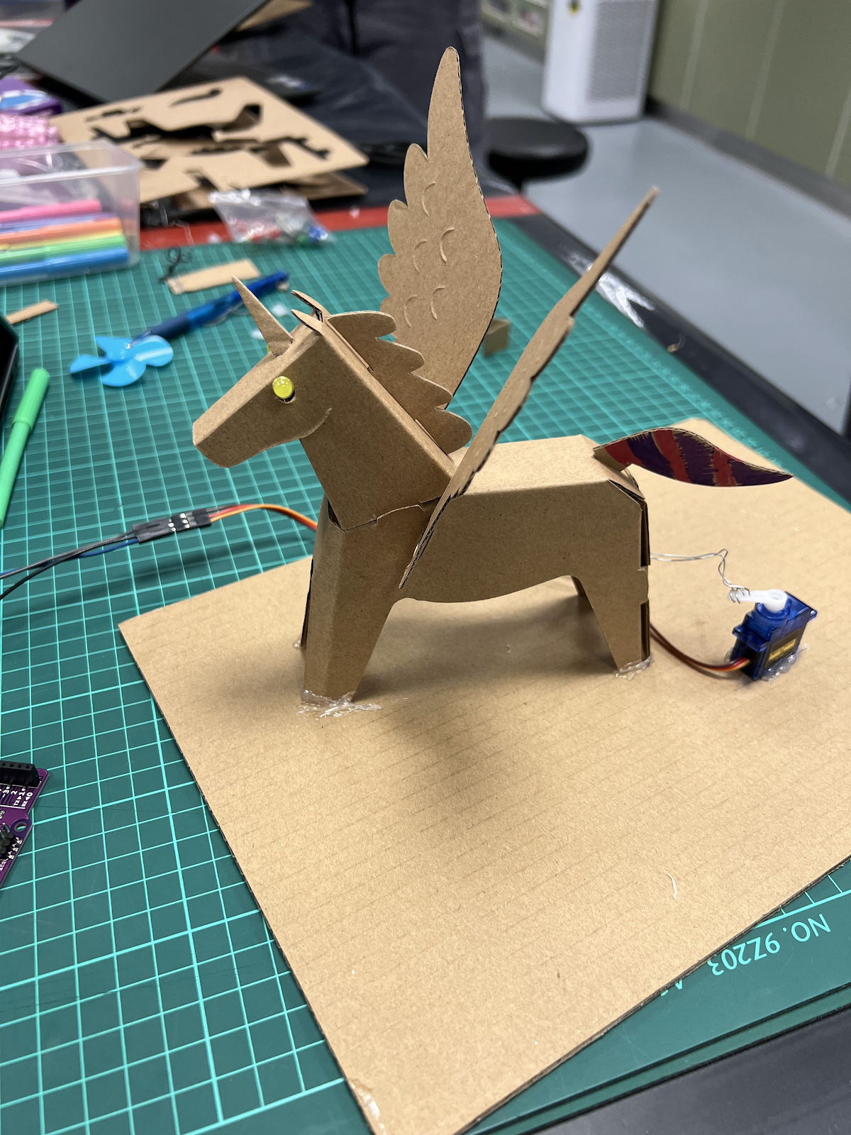
During the actual practical itself, my original group of 5 was separated into 2 groups, consisting of 2s & 3s. The group I was in consisted of me and my indian buddy Senthilu also known as Sreenithi. I was actually dumbfounded when the practical assignment was being announced. We were told create a code to allow the wings of the cardboard unicorn move. ***BONUS PART*** we had to add aesthetics to the unicorn to make it look better.
We started of by adjusting the angles moved by the servo and try to find the most natural looking flapping motion for the wings. We had actually tested so many different speeds and angels that during the practical itself the servo provided to us had burnt out, meaning that we had to get a new one just to continue our code. Next, we were thinking of how to attach the unicorn to the base cardboard plate that they had provided. Luckily, we had Matthias was in the 3 person group teach us how to tie rubber bands in a way that tension is added and that little movement from the servo would allow the wings to flap well.
However, after fiddling around with the unicorn and deciding on the final placements, we had noticed that the knots had come lose and were not as effective as they were at the start, so we moved the servo further away to give extra tension to the rubber bands attached to the unicorn.
The best part of the practical was how I took an inspiration from another group to of using music as the aesthetics component. Luckily, they had not realised that the learning package for the arduino practical had actually provided a zip file with multiple songs inside. I recalling the plans I was going to do on Christmas I had decided to use the Merry Christmas song to make our unicorn look nicer.
One disappointment that we had was that, despite both codes being correct we could find a reason of why the flappings of the wings flow the speed of the notes from the songs, making our flapping look unnatural but all in all it was a success and it also help inspire other groups to use songs to do so.
One take away I took from the practical was that, we should be able to learn and adapt to new situations in a short period of time. The arduino programming was introduced 2 weeks before the practical and we had to be able to understand and alter the code to make a UNICORN flap its wings ! and this adaptive mindset actually helped to realise that just because I study chem eng does not mean I will work as a chem eng and I need to be able to adapt to different varieties of job scopes to make myself versatile and fluid to my future employers
Here is a picture of our beautiful unicorn
and OFC we had to add the legend Mr Chua into our pictures
Pictures of me Senthilu and I
Thank you for tuning into this practicals blog and I hope that you enjoy the ones coming soon.
And lastly a meme to end it off


Comments
Post a Comment